How much do you know about fiber loss?
Do you know how to calculate it?
In fiber optic installation, accurate measurement and
calculation of fiber optic links are very important steps to verify network
integrity and ensure network performance. Optical fiber will cause obvious
signal loss (i.e. fiber loss) due to light absorption and scattering, which
affects the reliability of the optical transmission network. So how can we know the
loss value on the fiber link? This article will teach you how to calculate the
loss in a fiber optic link and how to judge the performance of a fiber optic link.
Type of fiber loss
Optical fiber loss is also called optical attenuation, which
refers to the amount of optical loss between the transmitting end and the
receiving end of optical fiber. There are many reasons for fiber loss, such as
absorption/scattering of light energy by the fibrous material, bending loss,
connector loss, etc.
Overall, there are two main reasons for fiber loss: internal
factors (i.e. the inherent characteristics of the fiber) and external factors
(i.e. caused by a fiber malfunction). Therefore, fiber loss can be divided into
intrinsic fiber loss and extrinsic fiber loss. Intrinsic fiber loss is an
inherent loss of fibrous material, which mainly includes absorption loss,
scattering loss, and diffusion loss caused by structural defects; Non-intrinsic
fiber loss mainly includes splicing loss, connector loss, and bend loss. To know
how to reduce these losses in fibers, you can visit "How to reduce the
different types of losses in optical fibers?" ".
Fiber optic loss standard
The Telecommunications Industry Alliance (TIA) and the
Electronics Industry Alliance (EIA) jointly formulated the EIA/TIA standard,
which specifies performance and transmission requirements for optical cables
and connectors, and is now widely accepted and used in the fiber optic
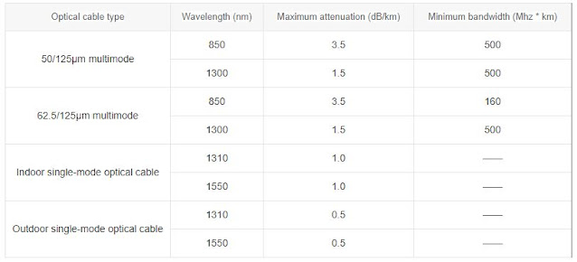
industry. The EIA/TIA standard specifies that maximum attenuation is one of the
most important parameters for measuring fiber loss. In fact, the maximum
attenuation is the attenuation coefficient of the optical cable, in dB/km. The
figure below shows the maximum attenuation of different types of optical cables
in the EIA/TIA-568 standard.
How to calculate fiber loss?
If you want to check whether the fiber optic link can work
normally, you need to calculate the fiber optic loss, power budget, and power
margin. The calculation method is as follows.
Fiber loss calculation
In fiber optic cabling, it is often necessary to calculate
the maximum loss over a certain length of line. Fiber Optic Loss Calculation
Formula:
Total Link Loss (LL) = Optical Cable Attenuation + Connector
Attenuation + Splice Attenuation [Note: If there are other components (such as
attenuators), their attenuation values may be superimposed]
Optical cable attenuation (dB) = maximum optical fiber
attenuation coefficient (dB/km) × length (km)
Connector Attenuation (dB) = Number of Connector Pairs ×
Connector Loss (dB)
Splice Attenuation (dB) = number of splices × splice loss
(dB)
As the above formula shows, the total link loss is the
maximum sum of the worst variables in a piece of fiber. It should be noted that
the total link loss calculated in this way is only a hypothetical value since
it assumes the possible value of the component loss, i.e. the actual fiber loss
depends on various factors, and the loss value may be higher or lower.
Let's take a practical case as an example to show how to
calculate fiber loss. As shown in the figure below, single-mode fiber is
installed between the two buildings with a transmission distance of 10km and a
wavelength of 1310nm. At the same time, this fiber has 2 ST connectors and 1
fusion splice.
Attenuation of optical cable - according to the standard
table above, the maximum attenuation value of an outdoor single-mode optical
cable with a wavelength of 1310 nm is 0.5 dB/km, so the d value of optical cable
attenuation is 0.5 dB/km × 10 km = 5 dB.
Connector attenuation - because 2 ST connectors are used and
the maximum loss of each ST connector is 0.75 dB, the connector attenuation is
0.75 dB × 2 = 1.5 dB. In the actual calculation, the insertion loss of the
connector can refer to the specification value provided by the supplier.
Splicing attenuation specified in TIA/EIA standard, the
maximum splicing loss is 0.3dB, so the splicing attenuation is 0.3dBx1=0.3dB.
We can conclude that the total loss of the fiber optic link
is 5dB+1.5dB+0.3dB=6.8dB. Note that the above calculation method is only a
hypothetical value, if you want to get the most accurate loss value, use
optical time-domain OTDR reflect meter measurements. For OTDR Time Domain
Reflectometer
Power Budget Calculation
What effect does the aforementioned link loss value have on
the transmission of the entire link? Here we have to mention another parameter
closely related to the computer power budget. This parameter value is mainly
used to compare the calculated link loss value to ensure that the equipment is
installed correctly. Only when the link loss value is within the power budget
can the link operate normally. The power budget (PB) is the difference between
the sensitivity (PR) of the receiver and the power (PT) of the transmitter
coupled into the fiber, i.e. PB=PT-PR. Assuming the average transmitter optical
power is -15dBm and the receiver sensitivity is -28dBm, the power budget is
-15dB-(-28dB) = 13dB.
Power margin calculation
After calculating the link loss and the power budget, you
need to calculate the power margin (PM), which refers to the power available
after removing the link loss from the power budget, i.e. PM=PB-LL.
Also, take a 10km indoor single-mode fiber optic cable as an
example. According to the calculation above, its power budget is 13dB and the
link loss is 6.8dB, so the power margin is 13dB-6.8dB=6.2dB. The calculated value
is greater than zero, indicating that the link has sufficient transmit power.


.jpg)


Comments
Post a Comment